This is a description of how to build a cheap
regulated 3.3V power supply for your projects
- 3.85V to 13.2V input
- 3.3V output
- Max 250 mA out
- Shortcircuit and thermal protected
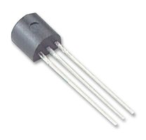
It is based on the MCP1702 3.3V Regulator,
which has internal current and thermal limiter.
TO-92 is the name of this kind of component Package (3 legs, flat top).
This is the Circuit we will build:

|
|
This Column is the fast track
|
This Column is for extra help
|
1
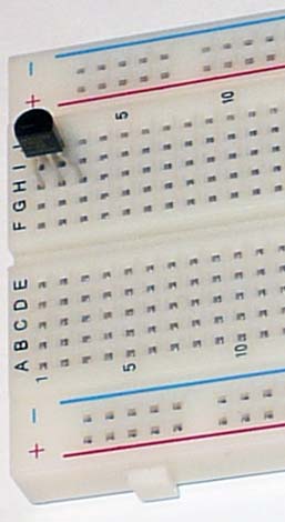
Bend the legs on the TO-92 to fit the board, and insert it in the board
|
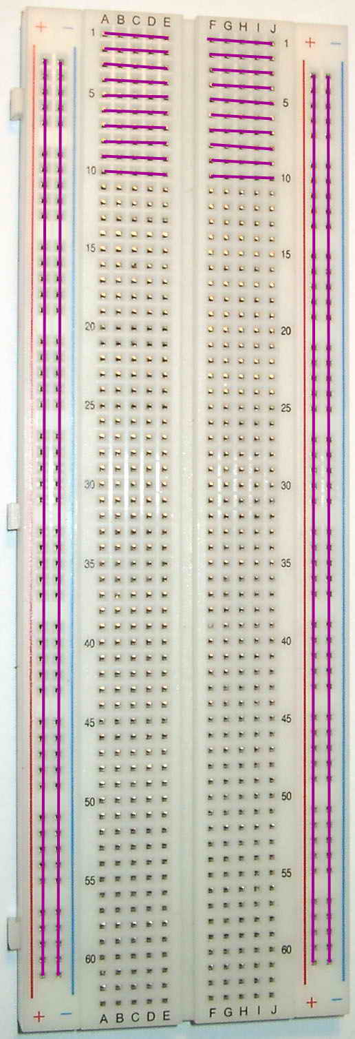
This is how this Solderless Breadboard is connected:
|
2

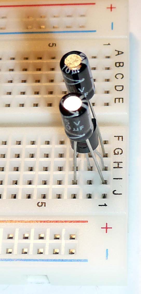
Connect the first 1 uF capacitor between PIN-1 and PIN-2 of the
TO-92
The side marked "-" should be towards PIN-1 (Ground).
|

This is an Aluminium Electrolytic Capacitor
"-" is to the left on this picture
You might need to cut the legs if they differ a lot in length.
|
3
Connect the second 1 uF capacitor between PIN-1 and PIN 3
The side marked "-" should be towards PIN-1 (Ground).
|
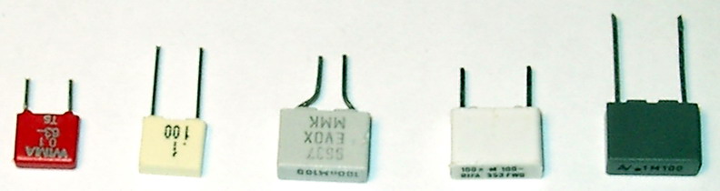
Capacitors can look pretty different, but all theese
are Polyester Capacitors of 100nF = 0.1 uF capacitance.
Which direction you connect them does not matter for
plastic or ceramic capasitors like theese.
|
4
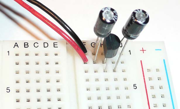
Connect the red lead of the Battery Snap
to PIN-2 and the black to PIN-1
|
Tweezers can help here.
|
5
Connect PIN-1 to the Ground Rail of the board (Blue or Black).
PIN-3 to the VCC Rail (Red)
|

If you are having trouble with stripping the wires,
use a Wire Stripper. :-)
(This is a 4$ model)
|
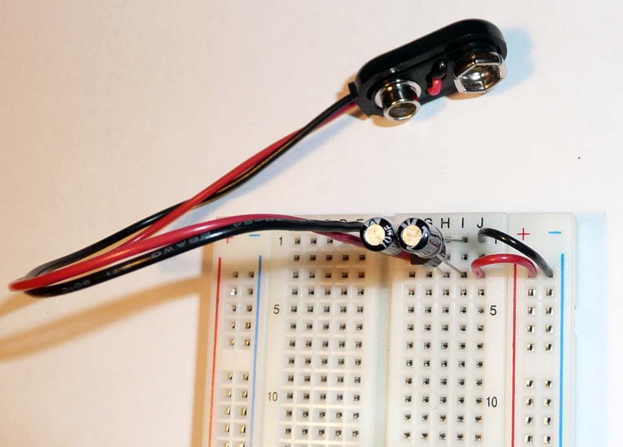
6
Connect this Ground rail to the Ground rail on the other side.
Connect the VCC rails
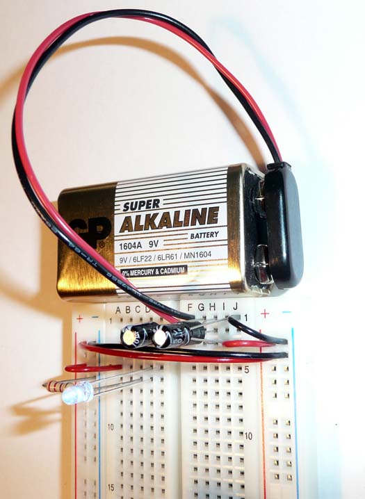
Test it with a LED
Connect GND through a 100 (to 1k) Ohm resistor, (in this case
we use the a 220 Ohm resistor), to the short leg of the LED.
The long leg of the LED to VCC of the board
Connect a 9V battery.
If the LED lights up, you got power.
If not, check that the LED is connected in the right direction.
(the long leg towards VCC).
Done!
|
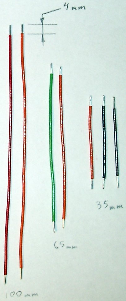
These are the wire lengths I use in my projects.
|
|
If you want to use any other powersource, you can connect
any DC source with a voltage output in the range between
3.85 and 13.2V
instead of the 9V battery.
Just connect Ground to PIN-1 of the Power regulator (TO-92)
(row 1, column F)
And + of your power source to PIN-2 = the middle pin on
the picture = row 2, column F.
|
|