How to connect the AVR
In this article the AT90S8535 is used, but ATmega8535 is pin-ekvivalent, and
everything is very much like described below, even if you use the most different
Atmel AVR's.
1
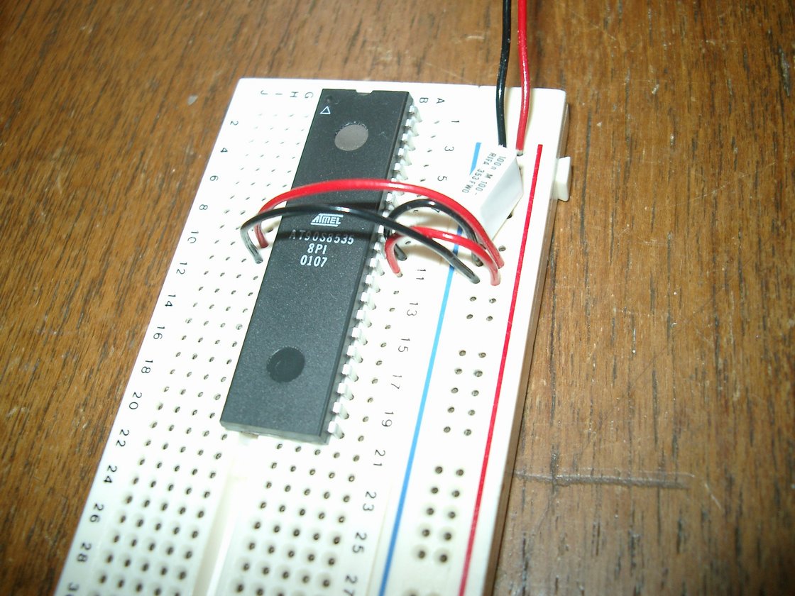 |
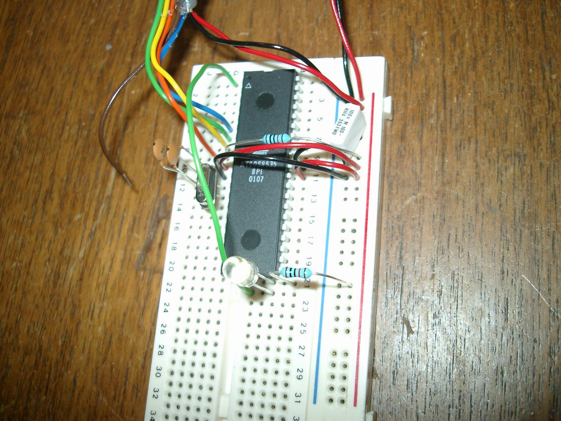
See the list for component values. You will need to adjust the MPU's leads to make it easy to put it on the board. When Vcc and GND of the MCU is connected to the Vcc and GND rails of the board and we have a decoupling capacitor in place, we don't need to worry anymore about static electricity. |
2
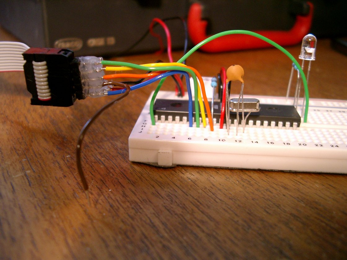
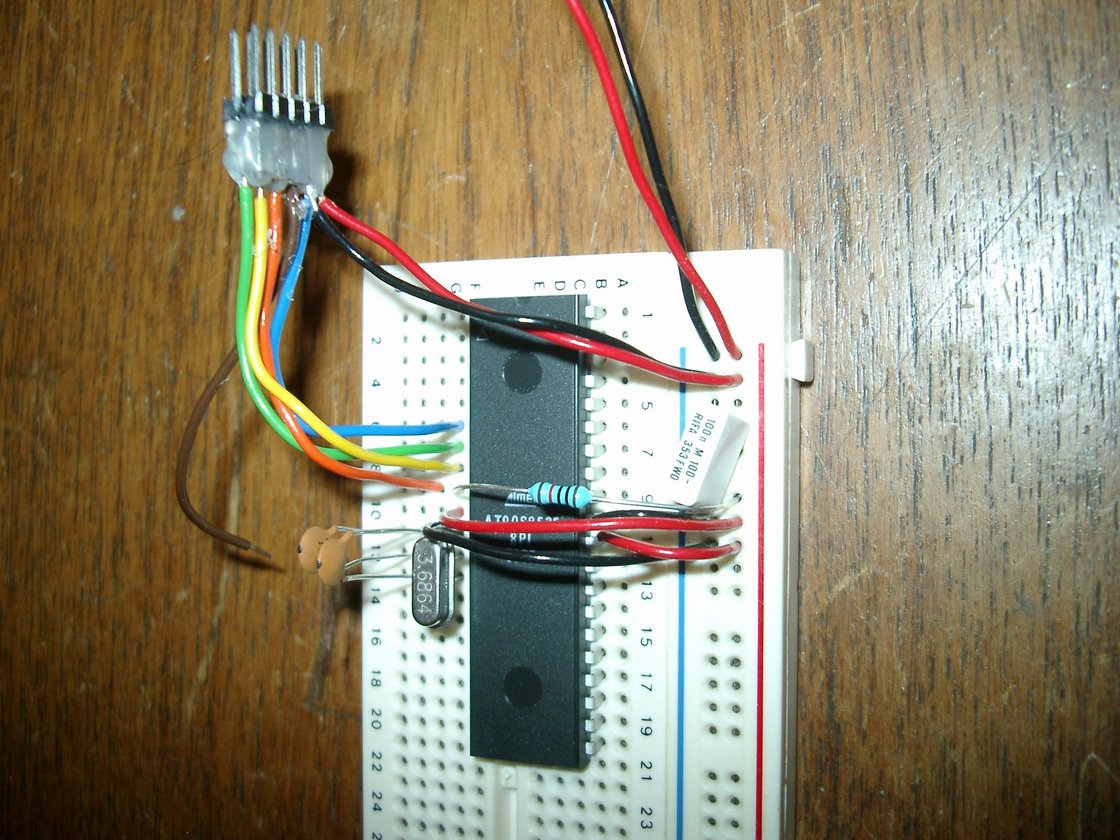 A crystal between XTAL1 and XTAL2. Capacitors between GND <-> XTAL1 and GND <-> XTAL2. Connect ICP-connector to MOSI,MISO,SCK,RESET,Vcc,GND. |
!RESET is active low, which means that we need to keep it high to keep the MCU from resetting all the time, but the programmer needs to be able to pull it low to write data to the MCU, this is the reason for the 10k resistor. The clock circuit consisting of the small capacitors and the crystall is connected to the clock driver pins of the MCU. As we see the programming interface uses some of the pins on PORTB, if we need to use them as inputs to the MCU, we need to put in 10k resistors to allow the programmer to force them low or high independent of the rest of the circuits on the board. We connect |
3
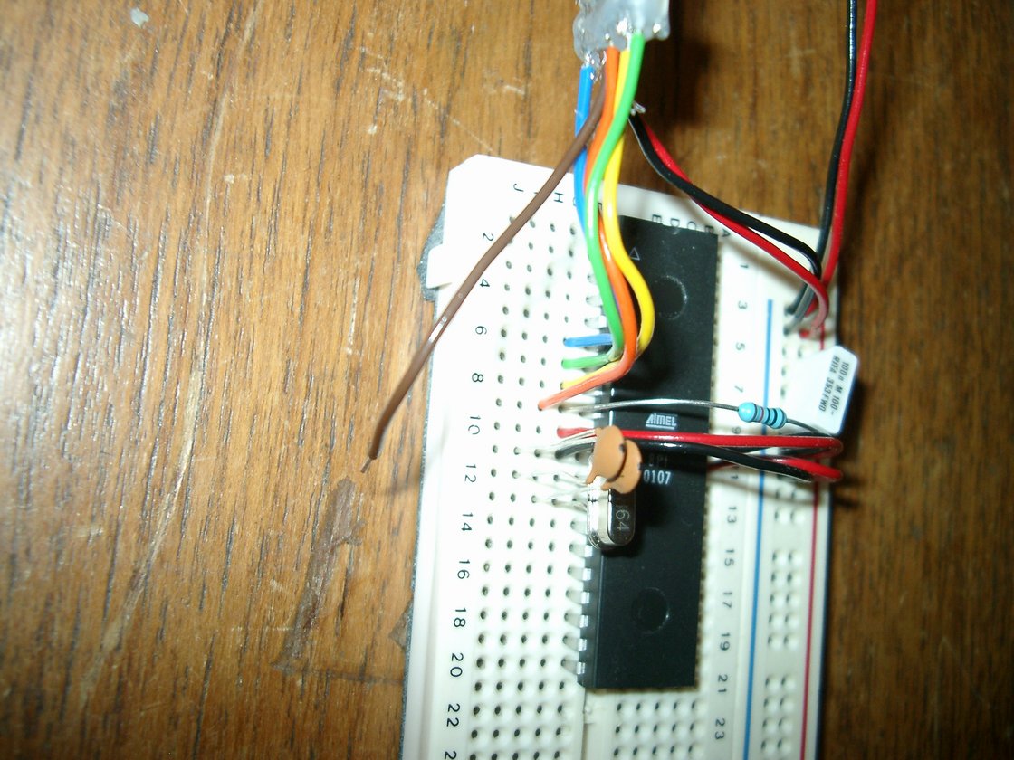 |
If you want a programming indicator, then connect a LED's short lead to the brown lead and the long via a 10k resistor to Vcc. But since we are hard core hackers, we watch the ports instead ;-) PORTB.0 to be precise = the LED we anyway need to test the MCU. |
4
 |
|
5
 |
|
6
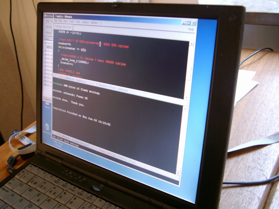 |
If you get an error message from "avrdude" it is likely your MPU is not running, check on XTAL2 to see if the clock is running. To not kill the clock while we meassure it, we need to first let it go through any circuit from the HC logic family . |