This is a description of how to build a cheap
regulated power supply for your projects
- 3.2V to 20V input
- 3V output
- Max 100 mA out
- Shortcircuit and thermal protected
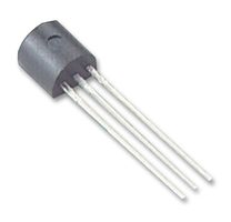
It is based on the LE30 (LE30CZ) 3V Regulator,
which has internal current and thermal limiter.
TO-92 is the name of this kind of component Package (3 legs, flat top).

This is the Circuit we will build:
|
|
This Column is the fast track
|
This Column is for extra help
|
1
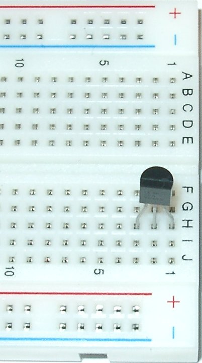
Bend the legs on the TO-92 to fit the board, and insert it in the board
|
This is how this Solderless Breadboard is connected:
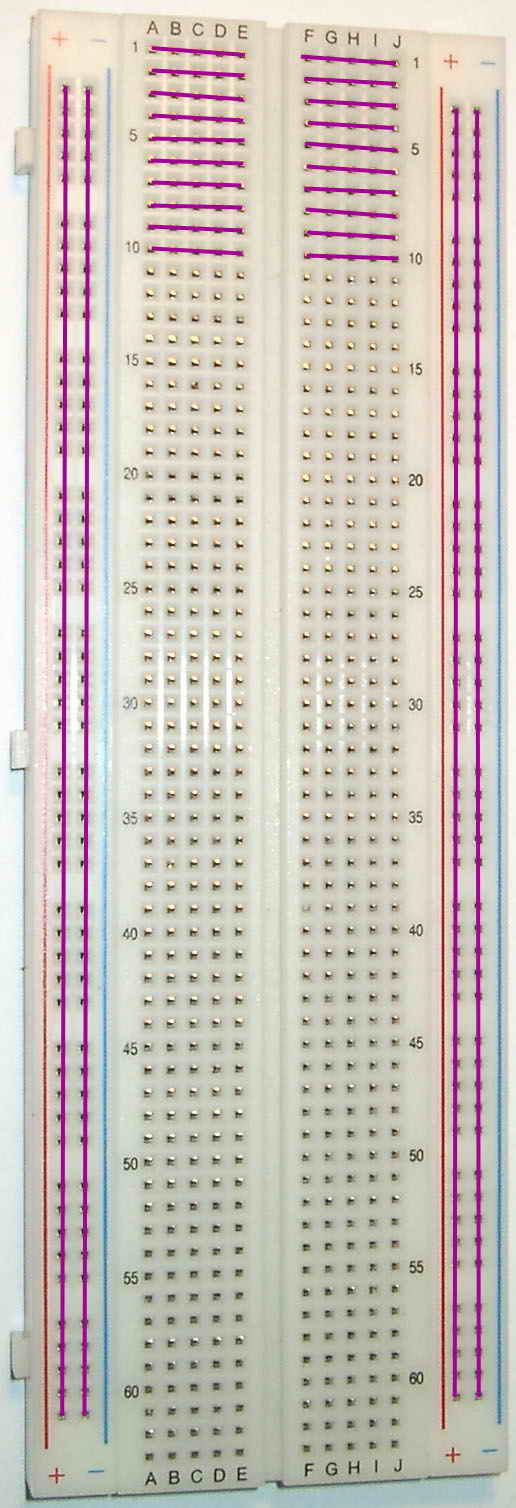
|
2
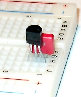
Connect the 0.1 uF capacitor between PIN-3 and PIN-2 of the TO-92
|
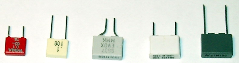
Capacitors can look pretty different, but all the
above are Polyester Capacitors of 100nF = 0.1 uF capacitance.
Which direction you connect them does not matter for
plastic or ceramic capasitors like theese.
|
3

Connect the 2.2 uF capacitor between PIN-1 and PIN 2
The side marked "-" should be towards PIN-2 (Ground).
|
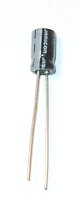
"-" is to the left on this picture
You might need to cut the legs if they differ a lot in length.
|
4
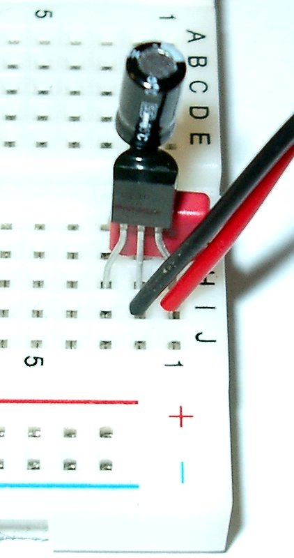
Connect the red lead of the T Style Battery Snap
to PIN-3 and the black to PIN-2
|
Tweezers can help here.
|
5
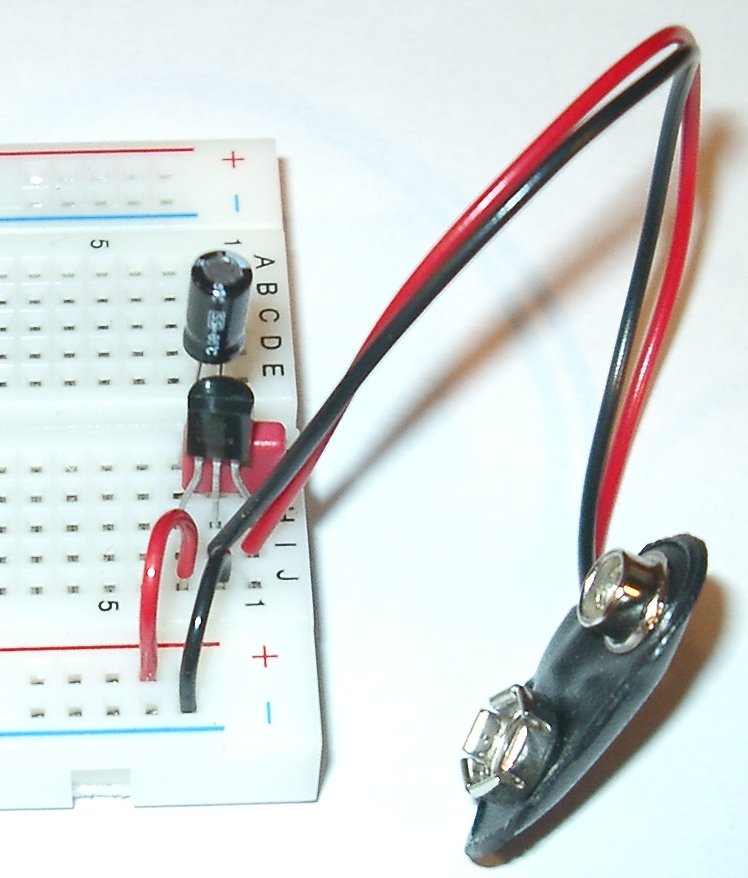
Connect PIN-2 to the Ground Rail of the board (Blue or Black).
PIN-1 to the VCC Rail (Red)

Connect this Ground rail to the Ground rail on the other side.
Connect the VCC rails
Test it with a LED
Connect VCC through a 150 Ohm resistor, (in this case
we use the kit's SIL resistor), to the long leg of the LED.
The short leg of the LED to Ground of the board
Connect a 9V battery.
If the LED lights up, you got power.
If not, check that the LED is connected in the right direction.
(the long leg towards VCC).
Done!
|
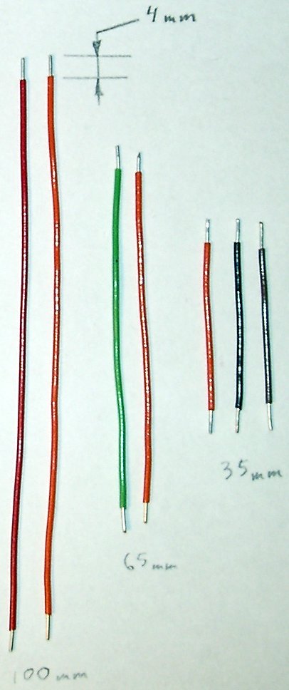
These are the wire lengths I use in my projects.
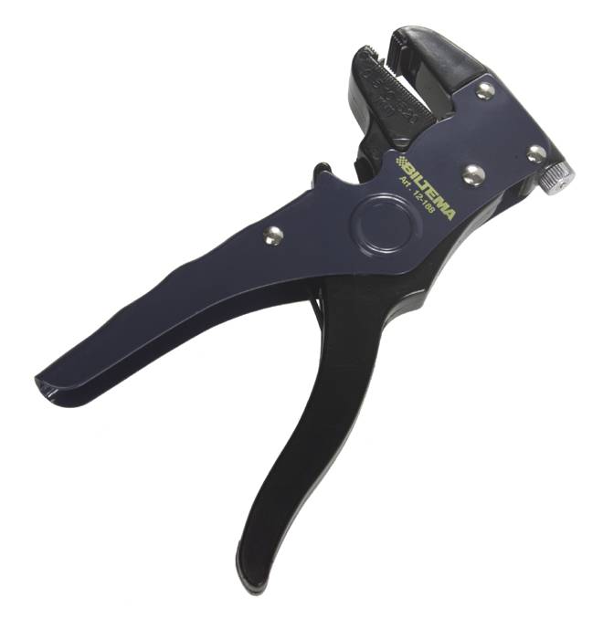
If you are having trouble with stripping the wire,
use a Wire Stripper. :-)
(This is a 4$ model)
|
|
If you want to use any other powersource, you can connect
any DC source with a voltage output in the range between
3.2 and 20V
instead of the 9V battery.
Just connect Ground to PIN-2 of the Power regulator (TO-92)
(row 2, column I)
And + of your power source to PIN-3 = the rightmost pin on
the picture = row 1, column I or J.
|
|