AVR Serial Port
| 1 Connect and get the MPU running according to the AVR standalone instructions, but put it in the middle of the Solderless Breadboard to make room for us to connect circuits both above and below it. |
|
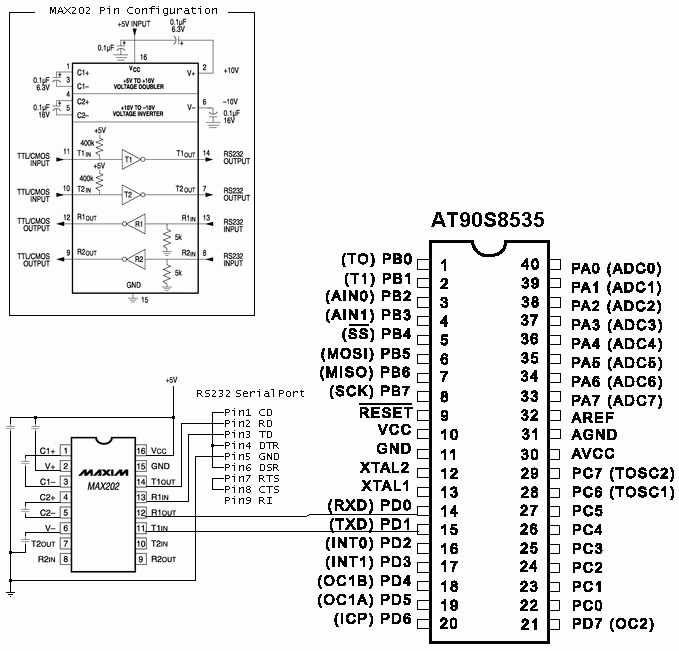
| 2 Conect the serialport of the computer via a signal level converter according to this image 
If you are using any other of the AVR MPU's, just connect it in the same manner: The MPU's TXD to T1IN on the MAX202. The MPU's RXD to R1OUT on MAX202. Connect the five 0.1 uF capacitors according to the image. As long as you don't use electrolytical capacitors it doesn't matter in which direction you connect them. |
|
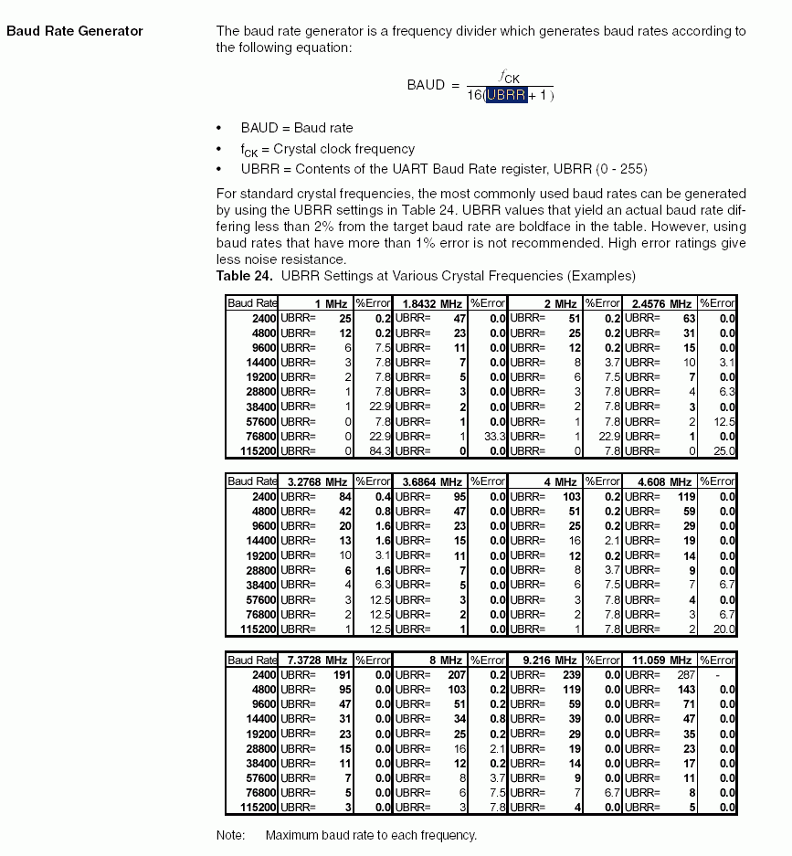
| 3 Program the AVR with this serial test program. As you can read in the inline documentation of the program, it echoes any character back over the serial interface, and sets PORTB to the value of the character. The testprogram was written using a 4 MHz crystal and a Baudrate of 19200. In the testprogram this corresponds to the line: InitUART according to the table below.
The table is from the UART section of the AT90S8535 doc.

InitUART(11);
|
|
| 4 Download and install Docklight, or any other serial communication tool, write over the serial line to the MPU, and with a little bit of luck, you get it echoed back :-) If you connect anything to the pins of PORTB of
the MPU, you might as well be able to see the bitts you are
writing to the MPU ;-)
|
Last modified: Wed Jun 08 00:12:35 W. Europe Daylight Time 2005