SMD Computer Controlled RGB-LED
DescriptionComputer controlled RGB-LED.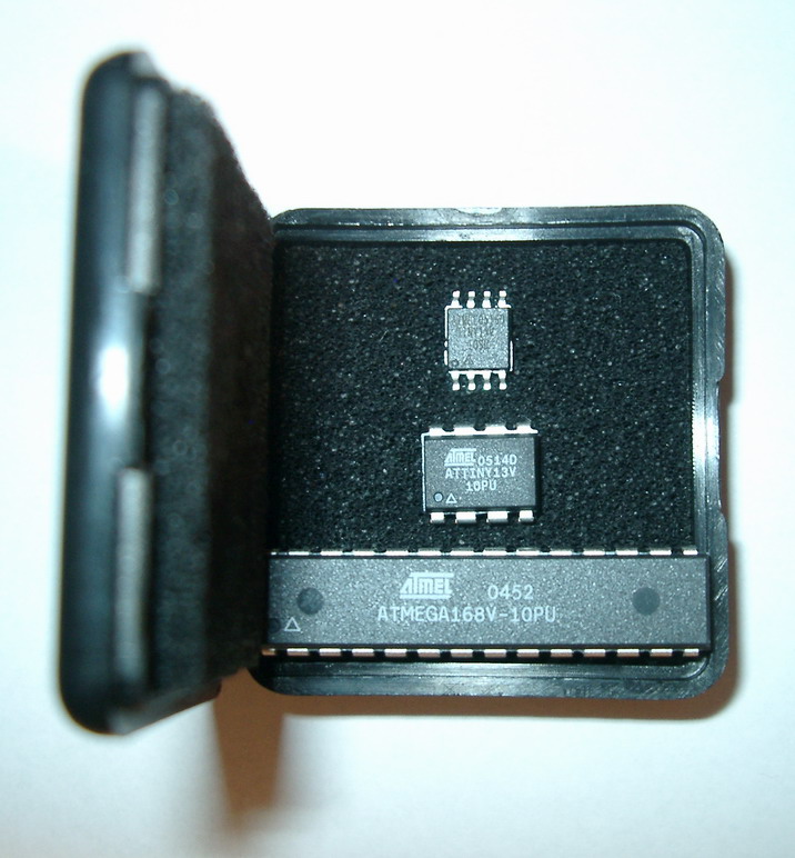
The ATtiny13 in SOIC package is pretty tiny :-) 
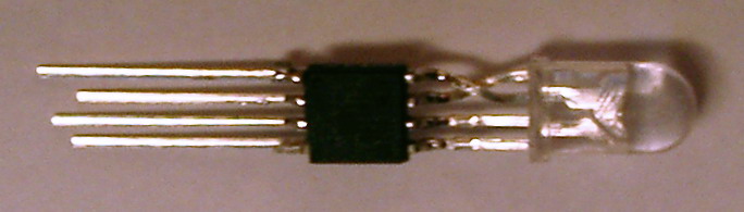
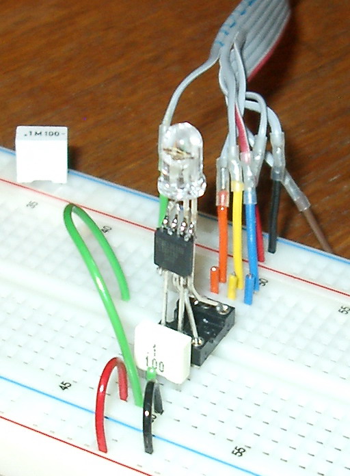
The RGB-LED has a common Anode, and 3 catodes, one for each color, in total 4 legs. Since the Anode did not match the AVR's layout, I bent the legs a little to switch legs, so that we have the anode closest to us on the picture. Then we just solder it to VCC on the AVR, and the 3k Ohm resistor between this leg and RESET. As you can see the VCC-PIN = PIN-8 is towards us at the left of the picture :-) RESET is to the right Notice the 3k Ohm resistor between RESET and VCC, we need this to be able to reprogram the AVR. Lets make it simpleIf we run the ATtiny13V on 3V, we won't need no resistors for current limiting, since the LED forward voltage's will eat up 2-3 Volt , and the current characteristics in the AVR data-sheet tells us it won't deliver to much current in this case (0-1 Volt over the PIN output since the LED).The quiestion is, will we get balanced RGB, or only red light, since the red diode has the lowest forward voltage? A practical test with an ATmega48V gave a positive result. If we program the device at 3V, we can allow the programmer to light up the LED, it won't destroy it at this low voltage during the short time it takes to program the device :-) If we run the device directly from a 3V battery, we will most likely not need any decoupling capacitor, since it might act as a capacitor, and we can accept strange behaveour from our colorful device, as long as it dosent reset itself constantly. So lets skip the cap to, since we anyway are skipping so many components :-) So, we have a LED, one 3k resistor and an ATtiny13V, if we only add a small 3V Lithium battery, we will have a complete programmable u-computer system, which can deliver an infinite number of colors :-) 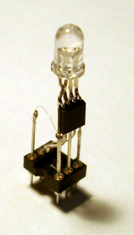
To be able to work with this AVR in my breadboard I had to mount it in a DIL-socket. Ugly, big, but simple to work with, and it is allway possible to cut the socket, and use a "gang-programmer" instead. (A gang-programmer will fit over the MCU, connecting to its legs, without any further needs of programming connections). 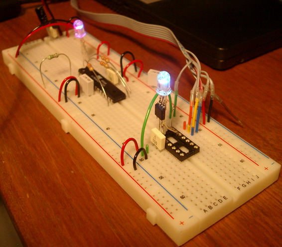
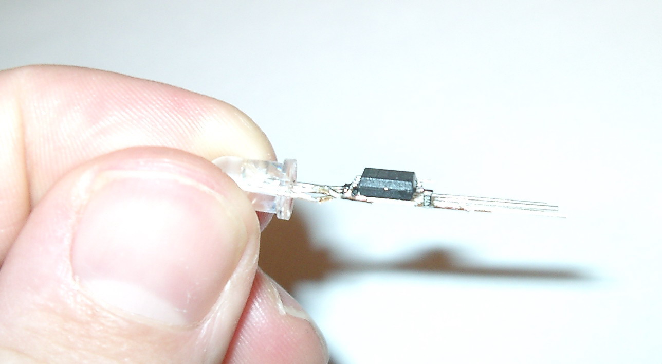
This is how bright it runs at 3V compared to the previous prototype that was using an ATmega48V with 220 Ohm resistors to each katode-leg of the RGB-led. When I meassured the current consumption of the circuit it used between 5 and 23 mA during the first colorcyckles. This was a little better then expected :-) A very lovely feature of this application is that the current consumption depends almost entirely on your software, and the max consumption in worst case of software is ok, that is: it won't damage the RGB-LED or the MCU Small Lithium batteries means that you have to use very small currents if you want to get the mAh that they were made to deliver, their output voltage drops very rapidly depending on the used current. But you can use a little larger currents during short pulses, see the data sheet from your Lithium battery producer. We will be able to handle this in software in a beautiful way. We might also have help from the fact that the MCU will run on 1.6V !, and the lowes forward voltage of the RGB leds diodes is 1.8V, so the MPU won't get "starved" easily when the battery is on its way to be depleted. If we use our experience from the Glowing Cocktail Stick we will see that 1 mA in average current would meet the manufacturers recomendations, but it seems common that devices abuse the batteries, e.g. I've seen LED lamps that are only a LED and a Li-battery. We might go for pulse-mode or test how our product behaves if we choose to abuse the battery and use more current. This is good input for the software design. The good side of it is that the LED was very bright at 23 mA, and if we design our product to make effective use of the avaiable light, then it will be sufficient for sure. 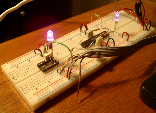
This program shifts the color constantly between "only" 16.7 million colors. It also runs on the free development kitt!You just have to change to the right MCU target in the makefile, as explained in the makefile or the sourcefile. Then you only need to connect 3 LED's one red, one green and one blue, or one RGB-LED instead of the 8 LED's that was connected to that kit, if you run the software first, then you see which LED's to change.Which battery should we use?Maby 2-3 zik-air batteries of type DA-10 1,4V 90mAh diametre 5,8mm, height 3,6 mm IEC = PR70, would be a good battery instead of the rather big CR1220 (diametre 12.4mm, h = 1.8mm). Or SilverOxide batteries of type 319 IEC = SR64 1.5V 20mAh diametre 5.8mm, height 2,7mm.

Oops, I did it again. (that is, stayed up late :-) Project completed in less then half a day including dockumentation. |
||||||||||||
Last modified: Sat Oct 22 04:01:12 W. Europe Daylight Time 2005