|
|
This Column is the fast track
|
This Column is for extra help
|
0
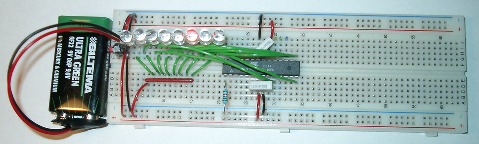
- Before you continue, you should have built the
Power Supply.
- If you only use the suggested wire lengths,
this and your future project will look better.
|
|
1

Insert the MPU at the exact possition you see on the picture.
Connect VCC and AVCC to your Positive
Power Rails (+)
And Both GND to Ground (-).
|
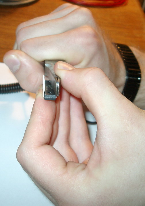

Adjust the legs to make it easy to insert the MPU into the Board.
Any bold text from now on, will usually correspond to a pin of the MPU,
see the pinout for the MPU above for description of which pin is which.
AVCC = Analogue supply voltage, VCC = Digital supply voltage.
|
2
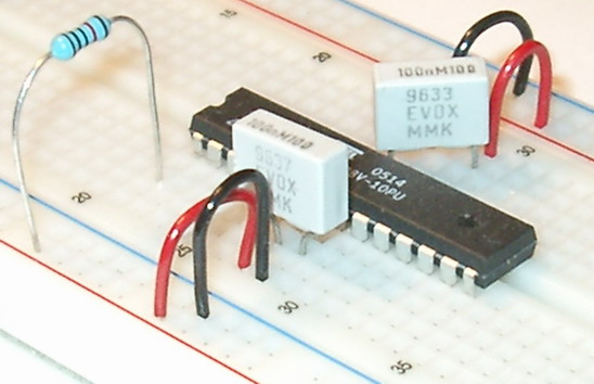 Put a decoupling capacitor between VCC and
GND.
Put a decoupling capacitor between VCC and
GND.
And an other one between AVCC and GND
Connect
RESET
to VCC by a (4.7k to) 10k Ohm resistor.
Make sure that power is connected to the power rails, and ground
to the ground rails.
|
|
3
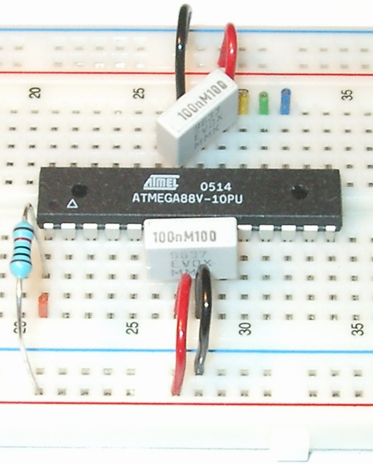
Later you will connect the Programmers VCC to VCC
GND to GND
Orange is RESET
Blue is MOSI = PIN-17
Green is MISO = PIN-18
Yellow is SCK = PIN-19
|
|
4
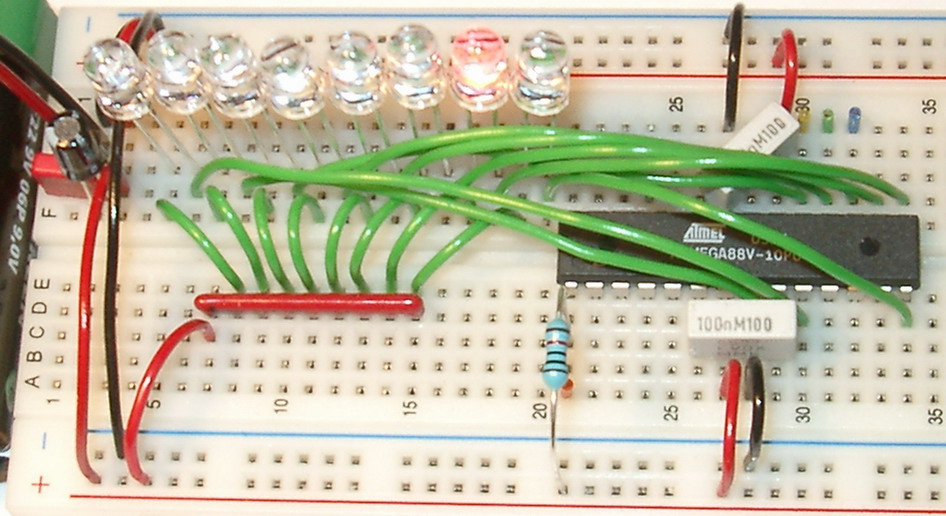
Connect the SIL-resistor's common terminal lead (marked black) to Vcc.
Connect the anode (long leg) of 8 LED's to each of the rest of
the SIL-resistors leads.
Connect the other lead of the LED that is closest
to the AVR to PB0 of the AVR. (see the pinout on the top of this page)
Connect the next LED to PB1, and so on, the last LED to PB7
|
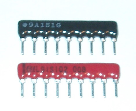
This is two SIL-resistors, the color does not matter,
note that the common terminal
(first pin from the left) it is marked with a black line on the red,
and a white dot on the black SIL.
Internally they are connected like the followning image illustrates:
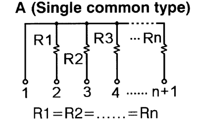
PB0 to PB7 is The AVR's PORT-B.
(see the AVR data sheet for more info about the MPU)
|
Congratulation!
If you have a programmer, you are done now.
If not, you need to build one next to the AVR MPU, then you can
start programming your system
|