-
Be prepared that if it was a while since the
last time you worked with stripping wires,
it will take suprisingly long time. It is a
good idea to buy a cheap Wire Stripper
(like the one on the Power Supply page).
- You only need the wires that corresponds to
pin 2 to 12 and pin 20 to 25 (see step 0.6 below).
|
|
|
This Column is the fast track
|
This Column is for extra help
|
| 0.1
|

|
| 0.2
|
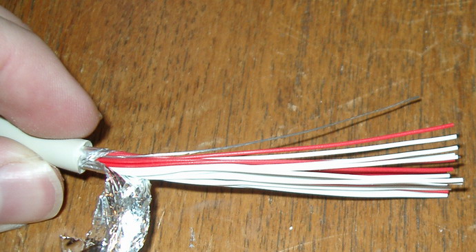
Cut the Parallel cable in half.
|
| 0.3
|
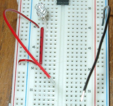
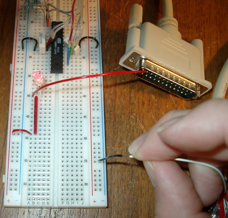
To find out which cable-lead that corresponds to which connector lead you need to:
Build a lead tester
Connect one side of the SIL resistor to Vcc.
The other side to a LED's cathode (the long leg)
The other leg of the LED to a red testcable.
And the other testcable to ground
|
| 0.4
|
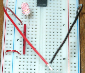
If you connect the testcables, the LED should light up.
|
| 0.5
|
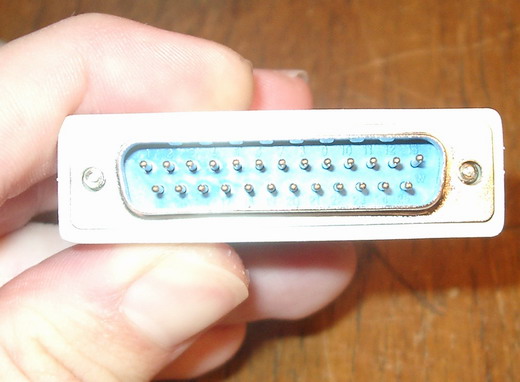
The connectors leads are numbered from left to right: 1 to 13 on the upper row, and 14 to 25 on the lower row.
|
| 0.6
|
Test which wire is which, and mark them with the same number as the corresponding connector pin.
Or if you are lucky, the wires all have different colors, then just write down colors
and corresponding pin numbers
You only need to label 2 to 12 and 20 to 25, you can use one label for 20 to 25, since they will be connected.
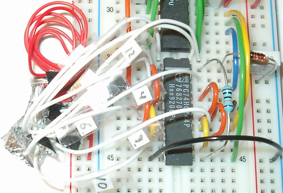
I taped numbers to the wires, as you can see at the last images.
|
| 0.7
|
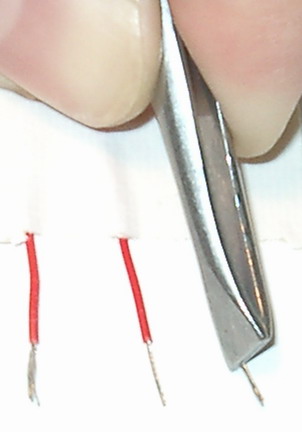
Inserting multicore wire into the Solderless Breadboard can be hard.
Twist the strands / leads together, and use tweezers.
The leftmost wire will not go into the board, the second is twisted,
the third is twisted and held right with a pair of tweezers
If you have a new breadboard, it might help to insert something else
first into the hole that you want to insert the multicore cable, since
new boards are extra tight.
If you get poor results, buy a cheap little soldering iron and
apply solder to the wire-tips before inserting them with the tweezers.
|
1
Insert the 74HC244 into the board.
HCxx = The 74HC244's PIN xx
For PIN numbering, see the image at the top of this page
|
Leave one row free between it and the Processor.
|
2
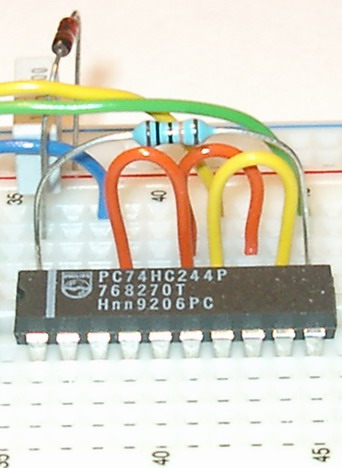
Connect HC20 via a 100k Ohm resistor to HC11.
Connect the Vcc-rail through a 1N4148 diode to HC20, black marking towards the 74HC244.
Connect HC20 to one lead of a decoupling capacitor (0.1 uF), and the other lead to Ground
Connect HC18 to the AVR's MOSI (blue)
Connect HC17 to HC15 (orange)
Connect HC15 to HC13 (orange)
Connect HC14 to HC12 (yellow)
Connect HC14 to the AVR's SCK (yellow)
Connect HC11 to the AVR's MISO (green)
|
MOSI is blue
MISO green
SCK yellow
RESET Orange
and the Programming LED connection is brown
|
3
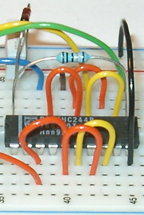
Connect HC07 to HC05
Connect HC05 to HC03
Connect HC03 to your AVR's RESET
Connect HC08 to HC06
Connect HC10 to Ground
|
The Orange connections connects the three paralleled driver's outputs to the MPU's
RESET
-PIN. All three is needed just to be able to sink or source enough current.
|
4
Fasten the Parallel cable to the board
Pxx = The Parallel cable PIN xx
Connect P20, P21, P22, P23, P24, P25 to Ground
|
|
5
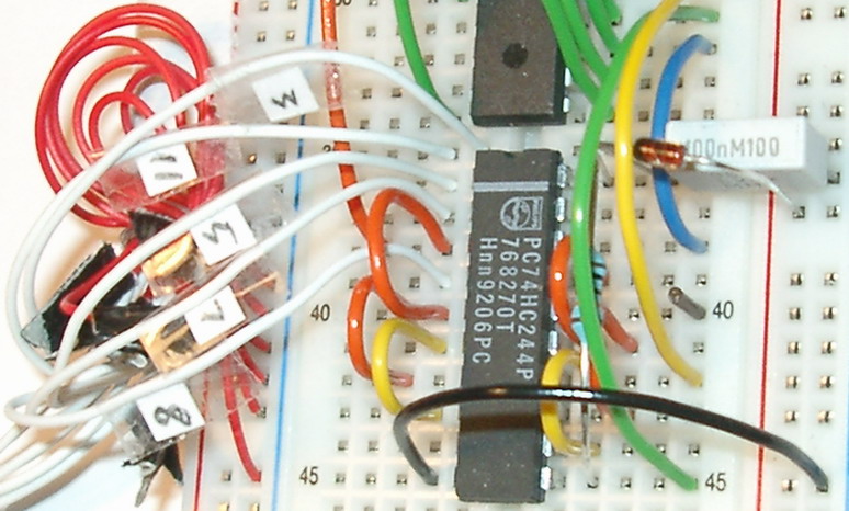
Connect P03 to P11 using unused boardspace
Connect P05 to HC01
Connect P07 to HC02
Connect P08 to HC04
|
|
6
Connect P12 to P02 by using unused boardspace.
Connect P04 to HC19
Connect P06 to HC06
Connect P09 to HC13
Connect P10 to HC09
|
|
7
Connect 74HC244 PIN-16 through a 820 Ohm resistor
to the anode (its long lead) of a LED.
Connect the LED's catode (its short lead) to Ground.
This LED will light up during programming of the AVR.
|
|
8
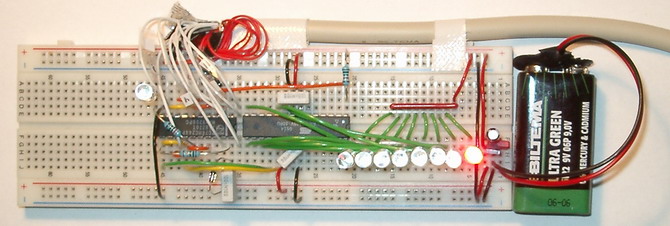
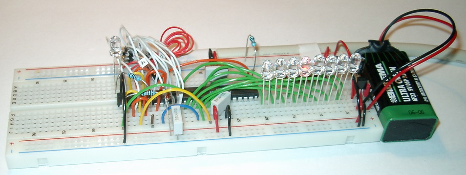
Congratulations!
Now we can start to program our system.
|

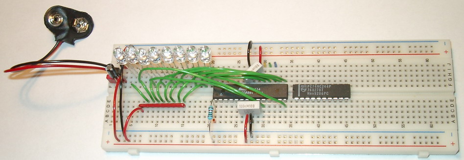
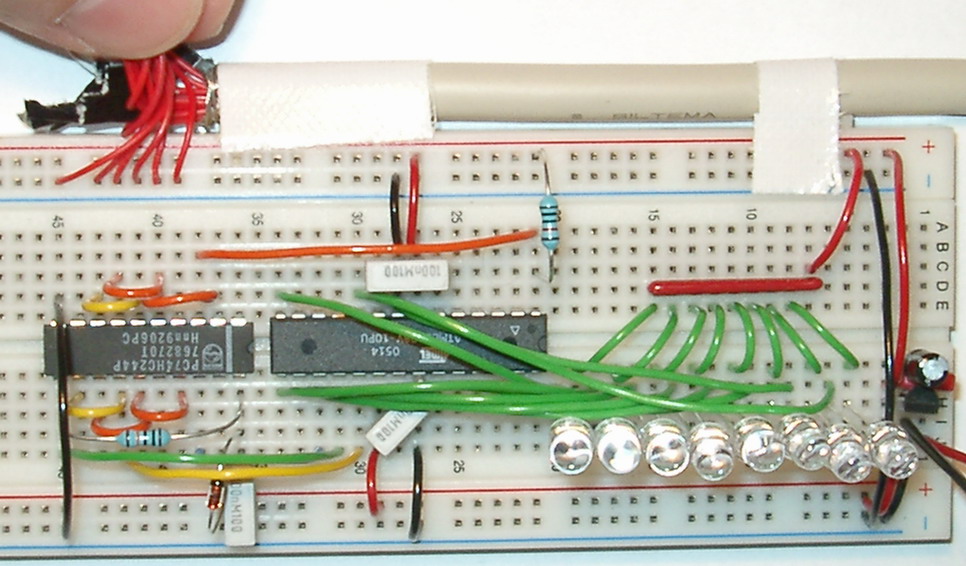
The programmer you have made is equvivalent with the standard STK-200
programmer (if we add some colorfull cables as on the image above).
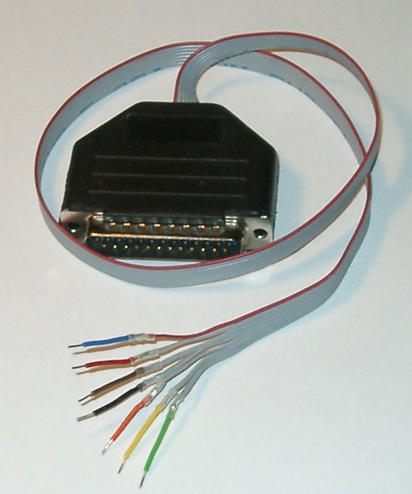
This is how our programmer can be made, if
soldered together and glued into a black DB-25 contact cover.
It works as well as having it on a breadboard, except that it does not
take up board-space.
|
| Blue | MOSI |
| Red | VCC |
| Brown | (optional) programming LED |
| Black | GND |
| Orange | RESET |
| Yellow | SCK |
| Green | MISO |
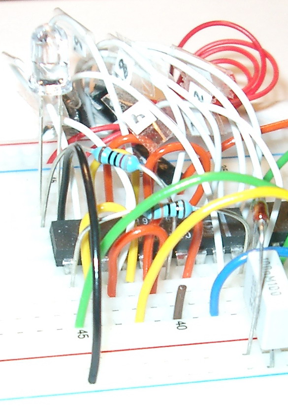
These are the cables you see above that goes from the 74HC244 at the left
to the AVR (to the right).
The STK200 and our programmer in the cable-cover, above to the right
has the same colors for the same signals.
E.g. the yellow and the blue cables in the center of the picture,
close to them the green. And on the other side of the IC's you can
see the fairly long orange RESET
line. The VCC and GND just goes to the boards VCC and GND.
The brown cable is missing, instead the resistor to the LED is connected
directly where it would be conected.
|