|
|
|
This Column is the fast track
|
This Column is for extra help
|
0
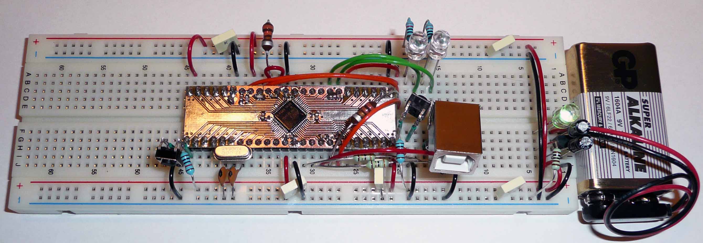
- Before you continue, you should have built the
Power Supply.
- If you only use the suggested wire lengths,
this and your future projects will look better.
|
|
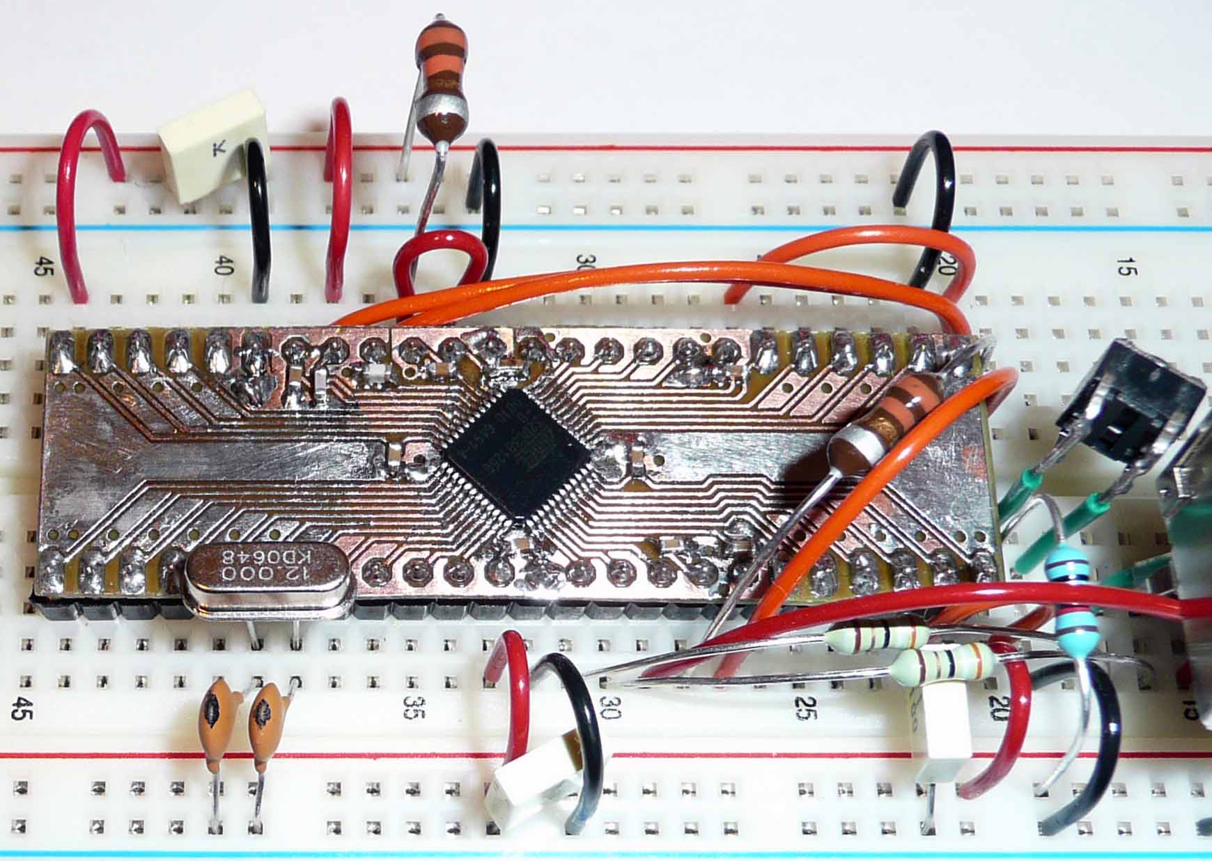
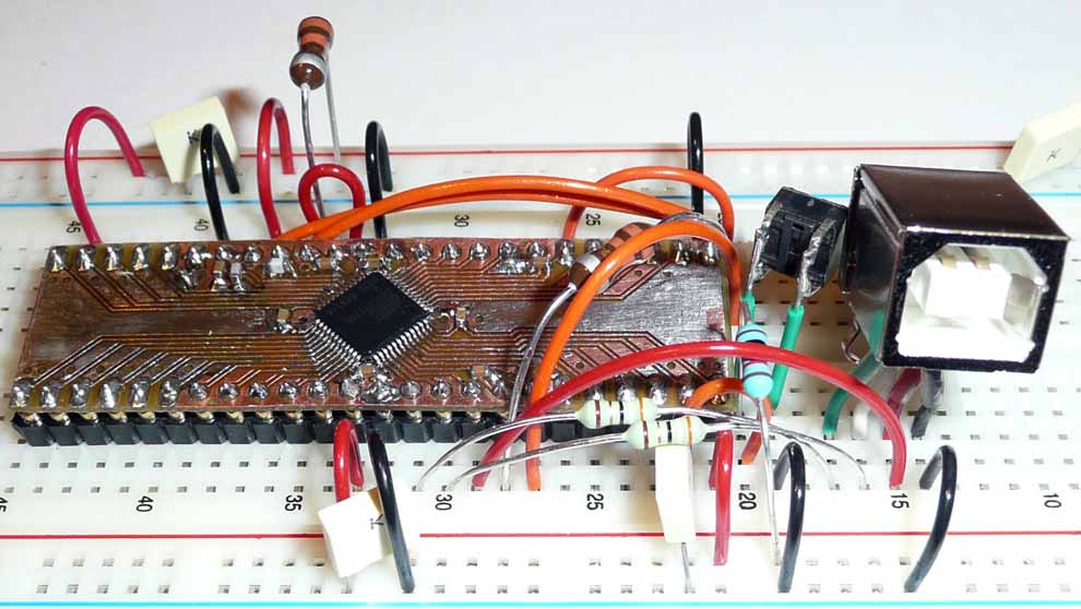
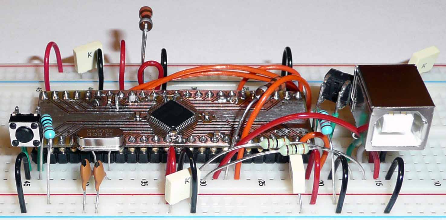
1
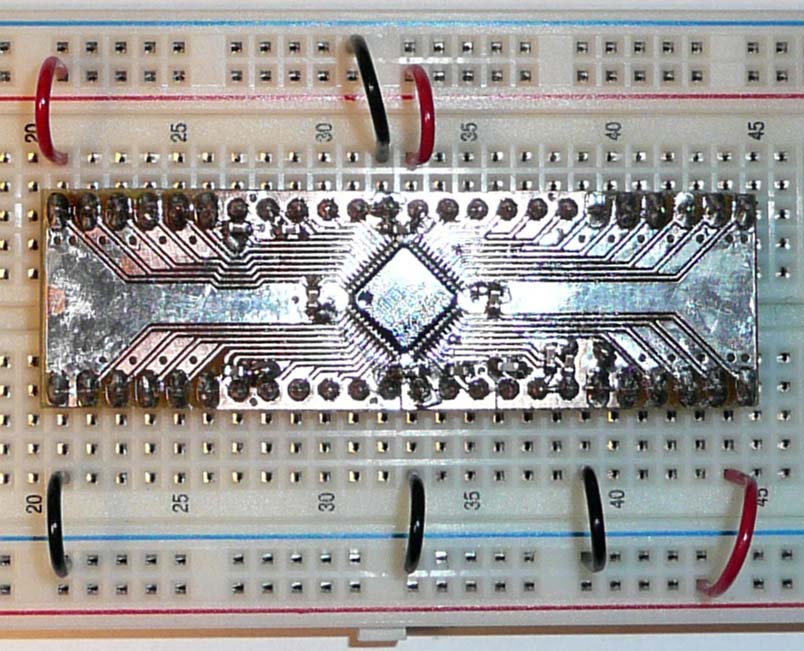
Insert the PIN to PIN Core
Module (AVR32 on DIL-48 board) at
the exact position you
see on the picture.
Connect GND PIN-1, PIN-19, PIN-33 and
GNDANA PIN 13 to Ground (-).
Connect VDDIO PIN-24, PIN-36, PIN-48 to your Positive
Power Rails (+)
Make sure that your powersupply supplies power to the power rails
(red), and that its ground is connected to the ground rails.
|
It is only for your conveniency that you can buy
the "AVR32 Core Board", if you prefer, you can
etch and make them at home, I have done so and
learnt a lot about etching and printing.
My best recommendation then is to use the component
values I have choosen in the schematics for the
"AVR32 Core Board", and to keep the capacitors
close to the power pins and to keep the tracks short.
You are free to copy anything here for your personal
use. If you on the other hand want to produce and
sell AVR32 DIL modules based on my design,
you may do so at a cost of 5%.
Please just contact me first to receive Gerber files
and/or the latest other production material.
On the other hand, you only need one AVR32 DIL Module
for your development, then when you go into production,
you can just switch to surface mounted technology.
So the need to design your own is minimal, and if
you want "AVR Core Boards" as a standard component
in your design, you are welcome. Your discount
will start at about 10% when you buy 10 units at
the same time, and reach the price limit of
production costs + 10% at 1000 units.
Our production will be very
efficient at 1000 or more units, so the price will
drop a LOT then. The production costs will go down
even more at 10k units, so your cost per unit will
keep decreasing all the way until we run out of silicon.
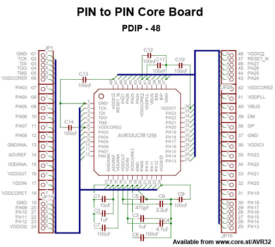
Any bold text from now on, will usually correspond to a pin of the MPU,
see the pinout for the MPU above for description of which pin is which.
VDDANA = Analogue voltage supply for the ADC, VCC = Digital supply voltage.
|
2
 Connect VDDIN PIN-17 to VCC
Add a couple of extra decoupling capacitors. (there are
already 14 of them on the DIL-48)
Make the 1.8V supply network in a
Star-topology
VDDOUT PIN-16 (1.8V) to an empty row on the
breadboard.
This will be our main VCC-1.8 node in our star,
from which we branch
out individual wires to feed each supply pin of the DIL-48.
Connect VDDCORE PIN-6, PIN-18, PIN-42 to the 1.8V row
(main node)
each with its own wire, (this powers us up).
Connect VDDPLL PIN-41 via a 3.3 uH Serial inductor
(the big dark brown thing that looks like a resistor) to the
1.8V row (main node).
|
Why star and inductor ? : see Star topology and
AVR32 AP7 Schematic Checklist.
The goal is to reduce noise on the supply lines.
|
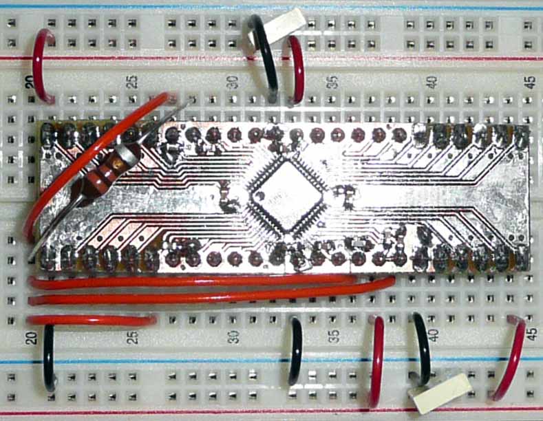
3
 Connect ADVREF PIN-14 to VDDANA PIN-15
Connect VDDANA PIN-15 via a 3.3 uH Serial inductor to
VCC
This is an effort to give a clean supply to the analog part
Connect a 100 nF capacitor between GND and
RESET PIN-47.
Connect
RESET
to VCC by a 10k Ohm resistor.
Connect
RESET
to a push switch to GND.
|
From EVK1101_Schematics_RevB.pdf
From AVR32715: AVR32 UC3B Schematic Checklist
|
4 USB Connection
The AVR32 can easily be programmed via its USB interface
DP PIN-38 through 39 Ohm resistor to USB-DP
DM PIN-39 through 39 Ohm resistor to USB-DM
VBUS PIN-40 to USB-VBUS
(USB host provides 5V when connected)
PIN-45 = PA26 is ID for USB OTG, we don't do OTG,
leave floating = we are B-device = Peripheral
Cable colors:
USB-D+ (Green) to DP PIN-38
USB-D- (White) to DM PIN-39
USB-VBUS (Red) to VBUS
USB-GND (Black) to GND
|
| PIN | USB Name | Cable colour |
Description |
| 1 | VBUS or VCC | Red | +5V |
| 2 | D- or DM | White | Data - |
| 3 | D+ or DP | Green | Data + |
| 4 | GND | Black | Ground |
More reading at:
http://en.wikipedia.org/wiki/USB_On-The-Go
|
5 12 MHz Crystal
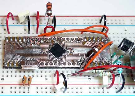
CPU Main Clock
Xin0 = PA18 = PIN-30 to crystall to
Xout0 = PA19 = PIN-31
Crystall legs to capacitors to GND
|
AT32UC3 devices are shipped with a USB bootloader
8,12 or 16 MHz Crystal is required on Osc0 (according to
USB DFU
bootloader.pdf)
Default USB DFU I/O start condition =
pressing the joystick on EVK1100
and EVK1101
|
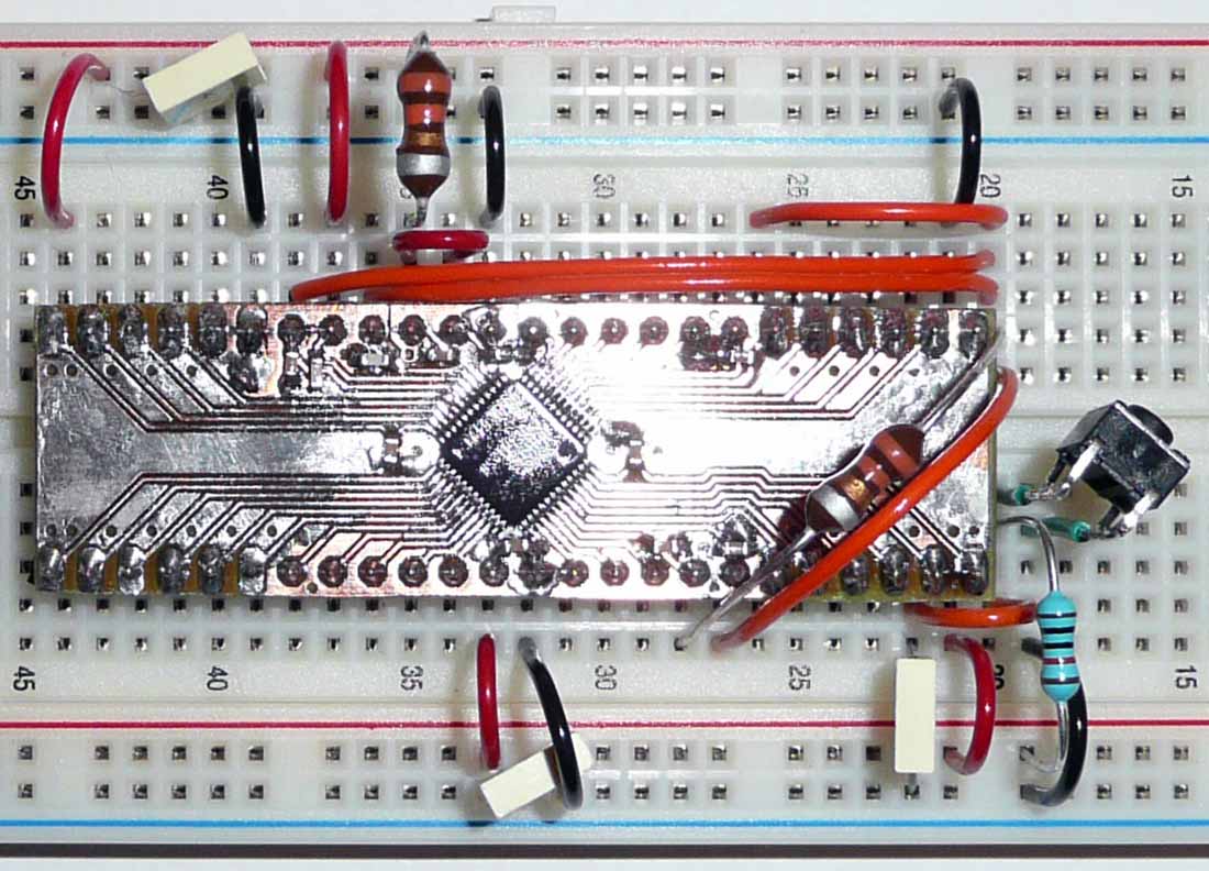
6 "Joy button"
We connect a button to PIN-25 = PA13, since this is
the PIN that the USB DFU Bootloader checks by default during
boot to select between
running the USB ISP or our program.
And we can also use this button as input in our programs
of course.
That is PIN-25 to a button which connects to
GND if you push it
PIN-25 through a 10k Ohm pullup resistor to VCC
|
|
6 LEDs
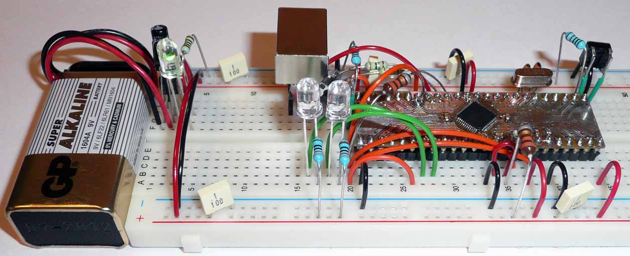
Connect PIN-7 = PA03 to the short lead of a LED, and
its long lead through a 820 Ohm resistor to VCC
Connect PIN-8 = PA04 to the short lead of an other LED, and
its long lead through a 820 Ohm resistor to VCC
Connect VCC to the long lead of a LED and its short lead
through a 1k Ohm resistor to GND. (This is only to show
if our device have power or not).
|
|

Congratulation!
Now you can connect it to your computer and
start programming it
with help of its USB DFU Bootloader.
|